Garrattfan's Modelrailroading Pages
OO9 NGG16
Chapter 9 Detailing (1)
Dec 2009 During the work on the cab/boiler assy I worked parallel on the detailing.
Go to Detailing page 2 Go to Detailing page 3 |
|
Boiler |
|

Drilling the boiler top holes. The boiler has a line scribed on the top (as per instruction Ch08.17) so this makes drilling the holes in the correct place easy (Dec 27,2009; Ch08.22) |
|

Polishing The safety valves will be blank brass later so I did some polishing, to the right an untreated valve |

Improvising Well here comes some criticism to the kit. I had two of the large devices at the right. These lost wax brass parts do not seem to fit anywhere in the description. Yet I lacked the injector and some other essentials. I snipped one of the two unknown thingies in two, using the the smaller halve as an ejector. |
The generator This white metal lump is supposed to be the generator. I would have preferred it to be cast in lost wax brass. Its attachment to the boiler was far too skinny so I drilled a 1 mm hole and soldered 1 mm brass wire in it to create a good support. I also snipped off the exhaust pipe and replaced it with 0,45 mm brass |

The improved genny |
The improved genny on its place cosily behind the steam dome. The parts have no yet been fixed in place. |

The genny on no 87 seen from the left rear side |

I also added some delicate tubing |
The would-be ejector. It is not fixed to the tubing downwards. This will be done after painting and more specifically after adding the boiler bands. |
| Next to to do were the handrails and the the stanchions | |

Drawing the boiler bands |
 |
| An easy way of drawing an approximation of the boiler band is using a straight, annealed strip of scrap brass | Keep it tight in a pair of pliers, adjust it to the pilot marking you made and draw a line . This line will give you guidance to place the stanchions and stay clear of the boiler bands. |

I attached the boiler with a rubber band and scribed one line on each side. Using the photos I took this summer I estimated the place of the stanchions. Note that the stanchions on no 87 are positioned a little different from the drawing supplied by Backwoods |
Murphy's Laws of modelrailroading:
|
Boiler backhead |
|
| I took assembling the firebox as an exercise of patience and tranquility | |
 |

The firebox door consists of five separate parts. The hinges and the handle are made of 0,3 mm brass wire |
 |
The regulator handle |

The boiler backhead casting has a distinct rim which does not show on my photos |

So I chiseled, filed and sanded the backhead to this result
|

|
|
Sanding the bottom of the backhead. To make it sit square and fair in the cab a small carpenter's square can be used. |
The backhead is really just about the size of a Euro coin |

The final result Three hours assembly time, 16 separate parts measuring 20 by 21 mm in all (Dec 31, 2009; Ch09.3). I also worked on other parts of the superstructure but I didn't make photos of every step, since building the brass frame/boiler assembly is relatively straight forward |
|
Next I added the various hatches in the ashpan. Tiny bits of work, don't seem much but to put them straight on their places needs some careful work. |

The boiler would not sit level on the frame as supplied. I had supposed it would but looking at the (thankfully still loosely assembled model) I got the impression that it did not sit level. Measuring it was difficult. My small caliper could not span the boiler. My large caliper would not fit under the frame between the ashpan and the various fittings in front of the ashpan. So I made a millimeter scale on the computer, printed it on paper and kept the assembly in front of it. And I was right, my eyes had not tricked me: the boiler slanted a little forward. As proof of that the smokebox door sank a little under the frame's top sheet. Difference from firebox to smokebox was less than 1 mm |

I devised a simple temporary help tool that would support the boiler at the correct height. This small help will be removed as soon as the boiler supports were fitted |

Here the boiler is positioned on top of the small helper. The smokebox door now stays clear of the frame's top |

I wanted the boiler/cab assy to remain separate from the frame to simplify the paint job later in the process. But attaching the boiler supports (which are in reality nothing of the kind) proved difficult. Every time I tried to solder them they slid away. I solved that by gluing them to the frame with a spot of CA superglue. |

Now the supports were temporarily fixed to the frame. The temporary support on the front has already been removed. Next I soldered the boiler on the supports. Once that was done I could gently break the supports from the CA spots. The support where firmly fixed to the boiler on exactly the right position, resulting in a level boiler laying dead on its frame. |

I started detailing the boiler. |

|
Supports are in place. Note that the supports have been shortened a little to match those of no 87. The steam exhaust pipes run in the same peculiar way as with no 87. The handle is also present |
I mused over the odd lay-out of this steam exhaust pipe leading from the cylinders to smokebox. I wondered what Chapelon and Porta would have commented on this rather narrow and sharply and multiple curved pipe. In my humble opinion this must lead to a higher back pressure on the cylinders, thereby reducing overall performance of the loco |

I blanked the rear cab side windows conforming to no 87.
|
 |
This loco also has a shorter cab but I decided not to copy that. Too risky, too much work. Since the model is inaccurate in several respects (flat front bunker top, the not extended rear bunker) I will be content to leave it this. Who will know after the model has been completed? Modelrailroading is, like many other disciplines, planning ahead. So, preparing for finishing the loco I ordered modern image lamps, used on no 87 when running on the WHR:
|
|

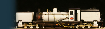
A view of the unfinished model with the lamp trial fitted to it |

The lamp in reality |
April 2, 2010: detail parts from Bowser have arrivedThe kit provides a generic set of detail parts. Given the specific no 87 I am building I needed other parts, especially the non-lifting injectors. Well, I found some that look very much akin with some cutting and filing, so I could pick up the work as soon as I received them. |
|
 |
First, this is the generator I bought from Bowser. Much better than the white metal model supplied with the kit |
 |
And this is the non-lifting injector, also from Bowser, Cary Detail Parts to be exact. |
 |
I cut off the piping and drilled 0,7 and 0,5 mm holes instead, as appropriate.
I inserted brass wire accordingly and soldered it solid. |
 |
What followed is nothing less than a Masterclass in the Martial Art of Pipe Bending. |
 |
Here's the prototype. It is not quite the same but this is about the best I can do. |
 |
The whole assembly has 13 bends, some of which are multi-dimensional. |
 |
I first wanted to omit the non-return valve in the water feed pipe towards the top feed. Having painstakingly bent the pipe until the footplate I was afraid I would only run into trouble by adding this valve. The prototype non-return valve (at the bulbous thing on the right in the copper pipe) |
 |
Leaving out the lost wax brass casting seemed a waste though. Pete McParlin didn't go through all his trouble to add this thing to the kit, just to have me omit it. So on second thought I found that adding this valve actually made things easier: soldered to the frame it will provide good support for both the injector and its piping and for the pipe between the valve and the top feed. First I modified the casting. I was way too long, I snipped the two extra small bulbs on the left and right side of the main bulb off. I also filed the hand wheel on the top down to its stem. I drilled two holes to hold the piping wire firmly. On the photo the modified version is already soldered to the frame, and the unmodded version below it for comparison.
|
 |
Next I soldered the top feed on the boiler to have a fixed reference point. Again holes were drilled at the appropriate places to pick up the wire.
|
 |
I snipped the feeder pipe short to attach to the non-return valve and made an all new pipe between the valve and the topfeed, passing prototypically clean under the handrails. I did not fix the piping because it will not be painted.
I took the piping off and stored it for later final assembly. Once the paint job has been done, I'll add these pipes and fix them with a little epoxy glue. Then the whole loco will be sprayed with a clear coat, for one to protect the sensitive thin paint coat and two to preserve the copper color of the pipes. |
| Go to Detailing page 2 | |


Sign my
GuestBook